- 您现在的位置:买卖IC网 > Sheet目录624 > FSBB15CH60C (Fairchild Semiconductor)IC POWER MOD SPM 600V SPM27CC
�� �
�
�Mini� DIP� (SPM3)� Application� Note� (2012-07-09)�
�6.3� Recommended� Wiring� of� Shunt� Resistor� and� Snubber� Capacitor�
�External� current� sensing� resistors� are� applied� to� detect� short-circuit� or� phase� currents.� A� long� wiring�
�patterns� between� the� shunt� resistors� and� SPM� will� cause� excessive� surges� that� might� damage� the� Mini� DIP�
�SPM� ’s� internal� ICs� and� current� detection� components,� and� may� also� distort� the� sensing� signals.� To� decrease�
�the� pattern� inductance,� the� wiring� between� the� shunt� resistors� and� SPM� should� be� as� short� as� possible.�
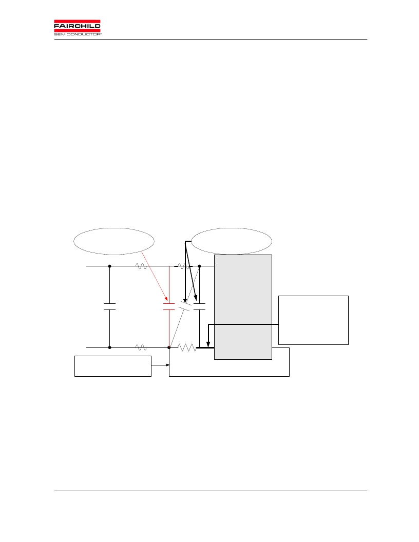
�As� shown� in� the� Fig.� 6.4,� snubber� capacitors� should� be� installed� in� the� right� location� so� as� to� suppress�
�surge� voltages� effectively.� Generally� a� 0.1� ~� 0.22� ?� F� snubber� is� recommended.� If� the� snubber� capacitor� is�
�installed� in� the� wrong� location� ‘A’� as� shown� in� the� Fig.� 6.4,� the� snubber� capacitor� cannot� suppress� the� surge�
�voltage� effectively.� If� the� capacitor� is� installed� in� the� location� ‘B’,� the� charging� and� discharging� currents�
�generated� by� wiring� inductance� and� the� snubber� capacitor� will� appear� on� the� shunt� resistor.� This� will� impact�
�the� current� sensing� signal� and� the� SC� protection� level� will� be� somewhat� lower� than� the� calculated� design�
�value.� The� “B”� position� surge� suppression� effect� is� greater� than� the� location� ‘A’� or� ‘C’.� The� ‘C’� position� is� a�
�reasonable� compromise� with� better� suppression� than� in� location� ‘A’� without� impacting� the� current� sensing�
�signal� accuracy.� For� this� reason,� the� location� ‘C’� is� generally� used.�
�Incorrect� position� of�
�Snubber� Capacitor�
�C�
�Correct� position� of�
�Snubber� Capacitor�
�P�
�Capacitor�
�Bank�
�A�
�B�
�SPM�
�Wiring� inductance� should�
�be� less� than� 10nH.�
�For� example,�
�width� >� 3mm,�
�thickness� =� 100� ?� m,�
�Wiring� Leakage�
�Inductance�
�Nu,Nv,Nw�
�COM�
�length� <� 17mm�
�in� copper� pattern�
�Please� make� the� connection� point�
�as� close� as� possible� to� the�
�Shunt�
�Resistor�
�terminal� of� shunt� resistor�
�Figure� 6.4� Recommended� wiring� of� shunt� resistor� and� snubber� capacitor�
�?� 2008�
�FAIRCHILD� SEMICONDUCTOR� -� Smart� Power� Module�
�28�
�发布紧急采购,3分钟左右您将得到回复。
相关PDF资料
FSBB15CH60F
MODULE SPM 600V SPM27-CA
FSBB20CH60CL
SMART POWER MODULE 20A SPM27-CB
FSBB20CH60CT
MODULE ADV MOTION SPM SPM27-CC
FSBB20CH60C
MODULE MOTION-SPM 600V SPM27-CC
FSBB20CH60SL
MODULE SPM 600V 20A SPM27-CA
FSBB30CH60F
IC SMART PWR MODULE SPM27-EA
FSBF10CH60BTL
MODULE SPM 600V 10A 3PH SPM27-JB
FSBF10CH60BT
MODULE SPM 600V 10A 3PH SPM27-JA
相关代理商/技术参数
FSBB15CH60C
制造商:Fairchild Semiconductor Corporation 功能描述:Transistor
FSBB15CH60F
功能描述:IGBT 晶体管 600V SPM RoHS:否 制造商:Fairchild Semiconductor 配置: 集电极—发射极最大电压 VCEO:650 V 集电极—射极饱和电压:2.3 V 栅极/发射极最大电压:20 V 在25 C的连续集电极电流:150 A 栅极—射极漏泄电流:400 nA 功率耗散:187 W 最大工作温度: 封装 / 箱体:TO-247 封装:Tube
FSBB20CH60
功能描述:IGBT 模块 HIGH_POWER
RoHS:否 制造商:Infineon Technologies 产品:IGBT Silicon Modules 配置:Dual 集电极—发射极最大电压 VCEO:600 V 集电极—射极饱和电压:1.95 V 在25 C的连续集电极电流:230 A 栅极—射极漏泄电流:400 nA 功率耗散:445 W 最大工作温度:+ 125 C 封装 / 箱体:34MM 封装:
FSBB20CH60B
功能描述:IGBT 模块 600V -20A 3-phase RoHS:否 制造商:Infineon Technologies 产品:IGBT Silicon Modules 配置:Dual 集电极—发射极最大电压 VCEO:600 V 集电极—射极饱和电压:1.95 V 在25 C的连续集电极电流:230 A 栅极—射极漏泄电流:400 nA 功率耗散:445 W 最大工作温度:+ 125 C 封装 / 箱体:34MM 封装:
FSBB20CH60BT
功能描述:IGBT 模块 600V -20A 3-phase RoHS:否 制造商:Infineon Technologies 产品:IGBT Silicon Modules 配置:Dual 集电极—发射极最大电压 VCEO:600 V 集电极—射极饱和电压:1.95 V 在25 C的连续集电极电流:230 A 栅极—射极漏泄电流:400 nA 功率耗散:445 W 最大工作温度:+ 125 C 封装 / 箱体:34MM 封装:
FSBB20CH60C
功能描述:IGBT 模块 600V 20A SPM
RoHS:否 制造商:Infineon Technologies 产品:IGBT Silicon Modules 配置:Dual 集电极—发射极最大电压 VCEO:600 V 集电极—射极饱和电压:1.95 V 在25 C的连续集电极电流:230 A 栅极—射极漏泄电流:400 nA 功率耗散:445 W 最大工作温度:+ 125 C 封装 / 箱体:34MM 封装:
FSBB20CH60CL
功能描述:IGBT 模块 20A, Motion-SPM
RoHS:否 制造商:Infineon Technologies 产品:IGBT Silicon Modules 配置:Dual 集电极—发射极最大电压 VCEO:600 V 集电极—射极饱和电压:1.95 V 在25 C的连续集电极电流:230 A 栅极—射极漏泄电流:400 nA 功率耗散:445 W 最大工作温度:+ 125 C 封装 / 箱体:34MM 封装:
FSBB20CH60CT
功能描述:IGBT 模块 600V 20A SPM
RoHS:否 制造商:Infineon Technologies 产品:IGBT Silicon Modules 配置:Dual 集电极—发射极最大电压 VCEO:600 V 集电极—射极饱和电压:1.95 V 在25 C的连续集电极电流:230 A 栅极—射极漏泄电流:400 nA 功率耗散:445 W 最大工作温度:+ 125 C 封装 / 箱体:34MM 封装: